
Projects
Vision-Based Environment Mapping and RRT* Path Planning in Simulation
1. Introduction
This project investigates a vision-based simulation pipeline for autonomous navigation in a 2D environment. The main objective is to convert an image of an environment into a binary occupancy grid and then use the RRT* (Rapidly-Exploring Random Tree Star) algorithm to compute an optimal path between a given start and goal location. This work integrates computer vision, environment representation, sampling-based motion planning, collision checking, and simulation, as outlined in the original project proposal. The motivation for this approach stems from real-world scenarios where robots must interpret visual information to construct maps and plan safe paths in unknown environments. By generating the environment directly from an image, the project eliminates the need for manually coded maps and demonstrates how perception and planning can be combined into a unified pipeline.
2. Methods
The first stage of the pipeline converts the input image into a binary occupancy grid (Figure 1). Each image is loaded in grayscale using OpenCV. A global threshold is applied such that pixels with grayscale intensity below the threshold are labeled as obstacles, while brighter pixels are labeled as free space. The threshold value was tuned empirically and set as 250. The output is a 2D NumPy array where: 0 represents free space and 1 represents obstacles.
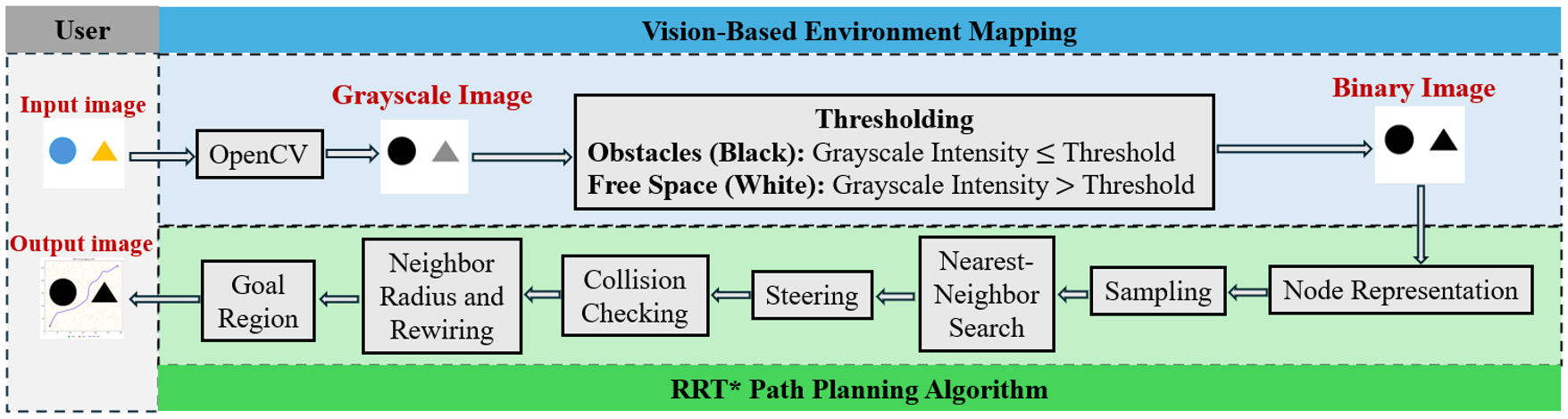
In the next stage, this grid serves as the foundation for collision checking during RRT* expansion. RRT* is an optimal variant of the RRT algorithm that incrementally improves path quality through rewiring. The implementation includes several steps: During the node representation, each node stores its (x,y) position, cumulative path cost, and parent index. Then, a free-space sample is generated by drawing random (x,y) coordinates until a location that is not an obstacle is found (sampling). Through the nearest-neighbor search, the closest existing tree node to the sampled point is selected based on Euclidean distance. The new node is placed at most 10 pixels (step size parameter) from the nearest node, preserving a controlled expansion rate (steering). A line segment between nodes is discretized and each point is checked against the occupancy grid to check collision. Therefore, any obstacle intersection invalidates the extension.
All nodes within a radius with γ = 80 and maximum radius 40 pixels are evaluated as potential parents. Rewiring is performed when a cheaper path to an existing node is found. Instead of requiring the new node to match the goal exactly, a goal radius of 15 pixels is used. When a node enters this region, it is considered a goal candidate, and the cheapest such node is used to extract the final trajectory (goal region).
3. Simulation and Results
All experiments were conducted in Python using OpenCV for image processing, NumPy for numerical operations, and Matplotlib for visualization. Parameters used across all the experiments shown in Table 1.
| Step Size (px) | Goal Radius (px) | Sampling Bias Toward Goal (%) | γ parameter | Maximum Neighbor Radius (px) | Maximum Iterations |
| 10 | 15 | 5 | 80 | 40 | 5000 |
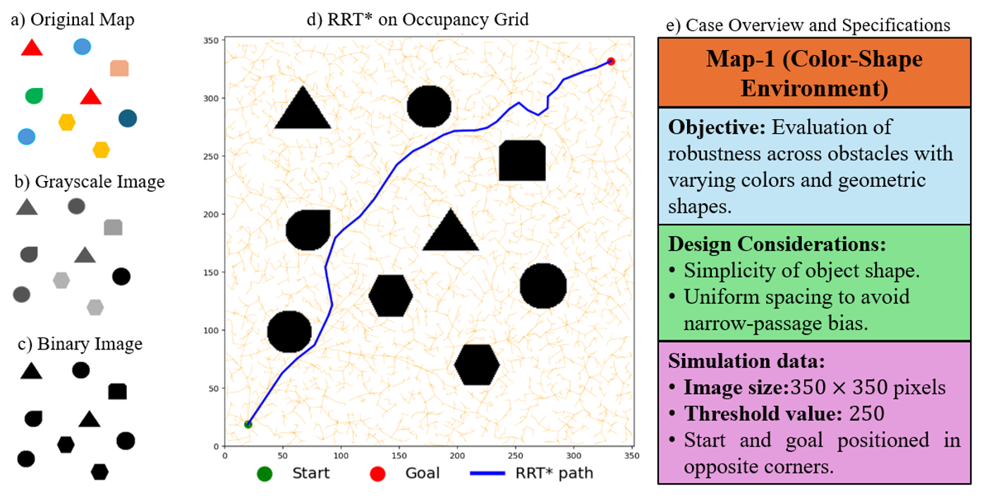
Two experimental cases were conducted to evaluate the robustness of the proposed vision-based RRT* motion planning pipeline. The case overview and specifications for the first scenario are demonstrated in Figure 2e. This map contains simple geometric objects rendered in multiple colors (Figure 2a; sketched using Microsoft PowerPoint) and is designed to demonstrate that the pipeline can correctly identify obstacles despite variations in color and shape. Initial threshold values (≈200) resulted in misclassification of lighter objects as free space, such as the yellow hexagons in Figure 2a. However, increasing the threshold to 250 enabled reliable segmentation of all obstacles, as illustrated in the binary output (Figure 2c) regardless of color or shape. Using this corrected occupancy grid, the RRT* planner produced a collision-free path that avoided every shape. Rewiring operations noticeably reduced path length and improved overall smoothness.
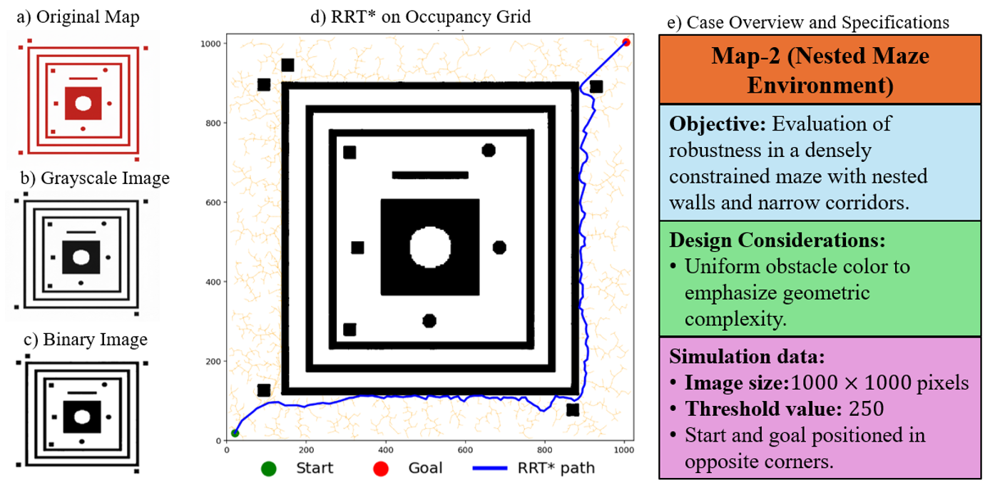
The second case, summarized in Figure 3e, examines performance in a geometrically constrained environment. This map, generated using an LLM (Gemini), features nested square corridors, narrow passages, and several interior obstacles (Figure 3a). The corresponding grayscale and binary images (Figures 3b-c) demonstrate that the vision pipeline accurately preserved fine structural details, including thin walls and sharp corners. Due to the restrictive geometry, the RRT* algorithm required additional iterations to explore detours and passageways; however, it consistently converged to a feasible solution (Figure 3d). Tree expansion was dense in open regions and naturally adapted to narrow corridors, demonstrating the planner’s ability to navigate complex environments.
4. Discussion
What Worked Well
The vision-based thresholding produced clean and consistent occupancy grids for both simple and complex environments. RRT* successfully found feasible paths across very different map geometries. Rewiring improved path smoothness and reduced path cost significantly. Parameter selection (step size, goal radius, γ) produced stable and consistent behavior.
Challenges and Debugging
Lower thresholds misclassified lighter obstacles, requiring tuning. Additionally, Matplotlib’s coordinate system needed inversion for consistent perception and visualization. RRT* terminated at the nearest node inside the goal region, so the visualization was updated to draw the final segment to the exact goal point.
Limitations
Global thresholding may struggle under uneven lighting or textured backgrounds. Incorporating edge-based image processing (e.g., Canny edge detection) and explicit robot kinematic constraints (such as a differential-drive model) could further improve robustness to complex visual inputs. Additionally, nearest-neighbor search slows as the tree grows because each new sample is compared against all existing nodes. More advanced search structures could speed this up in larger environments.
5. Conclusion
This project demonstrates a complete, simulation-based pipeline for converting arbitrary images into obstacle maps and performing optimal robot navigation using RRT*. The method successfully integrates perception and planning, operates across both simple and relatively complex environments, and produces visually and algorithmically robust paths. The results validate the effectiveness of combining computer vision with sampling-based motion planning for autonomous navigation in 2D environments.
Appendix: Code Repository
GitHub URL: https://github.com/Arifur-K/ME-556_Advanced-Robotics_Final-Project/tree/main