
Projects
Design and Implementation of a Finite State Machine for a Two-Floor Elevator System
Summary
This project focused on the design and implementation of a finite state machine (FSM) to control the operation of a two-floor elevator system with an objective of understanding how digital control logic can be used to coordinate sensors, user inputs, and actuators in a mechatronic system. Through this activity, we learned how to translate functional requirements into a set of discrete states, develop a state transition diagram, and implement the resulting FSM using an Arduino microcontroller. The project involved interfacing hardware components such as push buttons, optical interrupters, LEDs, and a motor driver with a microcontroller. In addition, the exercise highlighted the importance of handling invalid input conditions and incorporating an error state to ensure safe and reliable system behavior.
Hardware Overview
The design of a Finite State Machine (FSM) for a two-floor elevator system utilizes a wooden elevator kit, a DC motor, an external battery, a motor driver module, two push buttons, two LEDs, and two optical interrupters (Fig. 1). The elevator kit contains a hollow rectangular structure that functions as the elevator car. This car is actuated by a DC motor through a pulley mechanism, allowing the system to replicate the vertical motion of an elevator. The motion of the elevator car is controlled by adjusting the direction of rotation of the DC motor, which is powered by an external battery. Different FSM states correspond to different operational conditions of the elevator, such as moving upward, moving downward, or stopping at a floor.
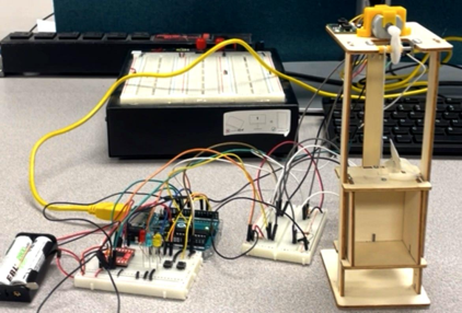 Figure 1. Hardware setup of the two-floor elevator system
The elevator system uses user inputs and sensor feedback to control motor-driven motion between floors. The system receives input signals from two push buttons and two optical interrupters. The push buttons act as control inputs that command the elevator to move either upward or downward by changing the direction of rotation of the DC motor. Two optical interrupters are positioned at the two floors to detect the presence of the elevator car. These sensors act as limit detectors, ensuring that the elevator stops when it reaches the designated floor. Three LEDs are used as status indicators: one LED indicates when the elevator car is at the upper floor, another indicates when the car is at the lower floor, and a third LED signals an error condition.
A motor driver module (SparkFun Dual TB6612FNG) is used to interface the microcontroller with the DC motor. Since a microcontroller cannot supply the current required to drive the motor directly, the motor driver acts as an intermediary circuit that amplifies the control signals. It allows the microcontroller to safely control the motor’s speed and direction by switching the polarity of the voltage applied to the motor. This functionality is essential for implementing the different motion states defined by the FSM.
Wiring
Fig. 2 shows the electrical wiring used to interface the sensors, control inputs, indicators, and motor driver with the Arduino microcontroller. The Arduino acted as the central controller of the system, receiving input signals from the push buttons and optical interrupters and producing output signals that drove the LEDs and the motor driver.
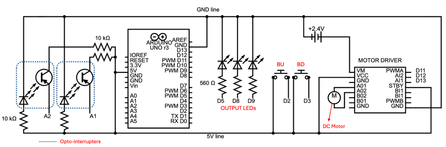 Figure 2. Wiring diagram of the elevator control system
The two push buttons for providing user commands were connected to digital input pins. The optical interrupters were connected to the Arduino through analog input pins and served as floor sensors. Each sensor was connected to 5V and GND using 10 kΩ resistors. A floor sensor read 0 when active and more than 20 otherwise. The three LEDs were connected to digital output pins through current-limiting resistors (560 Ω) to provide visual feedback of the system state.
The DC motor was driven using a dual H-bridge motor driver module [1]. The motor supply voltage was provided by a 2.4 V battery pack connected to the VM pin, while the driver logic was powered from the Arduino 5 V supply through the VCC pin. The AI1 and AI2 control pins were connected to Arduino digital output pins and determined the direction of rotation of the motor. The PWMA pin was also connected to a digital pin to set the motor speed to approximately 60% of full speed. The STBY pin was tied to 5 V to enable the driver during operation.
Designing the Finite-State Machine
A finite state machine (FSM) was designed to control the elevator system. The machine produces three possible outputs: GOING UP, GOING DOWN, and ERROR. Based on these outputs and the operational behavior of the elevator, five states were defined to represent the system conditions and transitions between floors. Table 1 summarizes the states and their meanings.
| State | Description | UP | DN | ERR | AI1 | AI2 |
|---|---|---|---|---|---|---|
| S0 | First floor | 0 | 0 | 0 | 1 | 1 |
| S1 | Going up | 1 | 0 | 0 | 1 | 0 |
| S2 | Second floor | 0 | 0 | 0 | 1 | 1 |
| S3 | Going down | 0 | 1 | 0 | 0 | 1 |
| S4 | Error | 0 | 0 | 1 | 1 | 1 |
The elevator can remain at a floor only when the button corresponding to leaving that floor is OFF and only the floor sensor at that floor is active. If the appropriate button is pressed while only the corresponding floor sensor is active, the elevator transitions from the floor state to a motion state. Any other combination of inputs while the elevator is stationary is considered invalid and causes a transition to the ERROR state. When the elevator is in motion, the only valid condition for continuing movement is when both floor sensors are OFF. The elevator is allowed to stop only when the sensor corresponding to the destination floor becomes active. Any other sensor input combination during motion is considered invalid and results in a transition to the ERROR state.
To ensure controlled recovery from faults, the system exits the ERROR state only when the user presses both buttons simultaneously and no more than one floor sensor is active. This condition ensures that the system resets only when the inputs indicate a valid configuration. Fig. 3 shows the state transition diagram of the designed finite state machine.
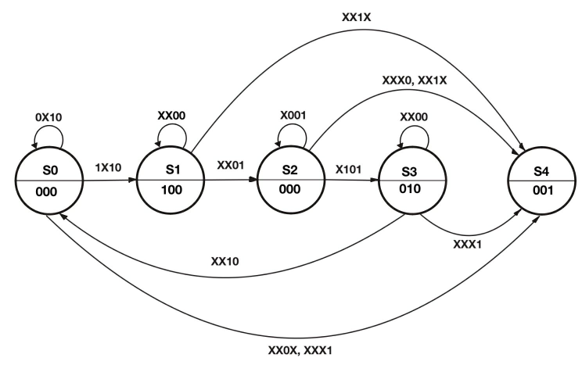 Figure 3. State transition diagram for elevator control system
The output for each state is also shown in Table 1. UP is active only when the elevator is going up; DN (down) is active only when the elevator is going down; while ERR (error) is active only when there is an error. These outputs are displayed to the user through LEDs and are also used to control the motor through the driver’s AI1 and AI2 control pins. Applying the products-of-sums method to the output combination in Table 1, the following relations can be obtained:
Arduino Implementation
The finite state machine was implemented on an Arduino microcontroller to control the elevator system. The program continuously read the inputs from the floor sensors and control buttons, determined the appropriate state transition according to the FSM logic, and updated the outputs that drove the motor control pins and LED indicators.
The implementation used a switch–case structure, where each case corresponded to one of the defined FSM states. For each state, a helper function determined the next state based on the current input conditions and the transition rules described in the FSM design. Once the next state was determined, a state-to-output mapping assigned the appropriate output values, which were then written to the LEDs to indicate system status and to the motor driver through the AI1 and AI2 pins to control the direction of motion.
Additional measures were incorporated to improve the reliability of the input readings. Mechanical push buttons can produce unintended rapid transitions, known as contact bouncing, when they are pressed or released. If these transient signals were interpreted directly by the FSM, they could produce invalid input combinations and potentially trigger the ERROR state. To mitigate this issue, a debounceButton function was implemented to ensure that at least 50 ms elapses between successive recorded changes in button input.
A similar challenge was observed in the interrupter readings. When the elevator begins leaving a floor, the interrupter may continue to report an active signal until the trigger fully exits the sensing region. However, the FSM logic requires the corresponding floor sensor to transition to OFF immediately when motion begins. To accommodate this physical behavior, the sensor readings were temporarily disabled for 0.5 seconds after the elevator starts moving. This delay ensures that the FSM receives sensor inputs that accurately reflect the intended state transitions.
Conclusion
In this project, a finite state machine (FSM) was successfully designed and implemented to control a two-floor elevator system using an Arduino microcontroller. The system integrated multiple hardware components, including push buttons, optical interrupters, LEDs, a DC motor, and a motor driver module, to simulate the operation of an elevator. By defining appropriate states and transitions, the FSM was able to manage elevator movement, detect floor positions using sensors, and handle invalid conditions through an error state. The implementation demonstrated how discrete control logic can be applied to coordinate sensors, actuators, and user inputs in a mechatronic system. The results confirmed that the FSM design provided reliable and predictable system behavior, illustrating the effectiveness of state-based control for embedded and automation applications.
References
- SparkFun Electronics, TB6612FNG Hookup Guide. Available: https://learn.sparkfun.com/tutorials/tb6612fng-hookup-guide
Appendix A – Arduino Code
enum State { S0,
             S1,
             S2,
             S3,
             S4 };

const unsigned int FFS_PHOTO1_THRESH = 10; // sensor activation threshold
const unsigned int SFS_PHOTO2_THRESH = 10;
const unsigned int DEBOUNCE_DELAY = 50; // ms
const unsigned int SENSOR_OFF_TIME = 500; // ms
const unsigned int MOTOR_SPEED_PERCENT = 60;
const unsigned int MOTOR_PWM_VALUE = (MOTOR_SPEED_PERCENT * 255) / 100;

// State-to-Output Map: {UP, DN, ERR}
const bool STATE_TO_OUTPUT_MAP[5][3] = {
  { false, false, false }, // S0 - Down
  { true,  false, false }, // S1 - Going up
  { false, false, false }, // S2 - Up
  { false, true,  false }, // S3 - Going down
  { false, false, true  }  // S4 - Error
};

const int BUpin = 2;
const int BDpin = 3;
const int FFS_photoPin = A1;
const int SFS_photoPin = A2;
const int UP_LEDpin = 5;
const int DN_LEDpin = 8;
const int ERR_LEDpin = 9;
const int pwmSpeedPin = 11;
const int motorAI1pin = 12;
const int motorAI2pin = 13;

// inputs
bool BU;
bool BD;
bool FFS;
bool SFS;

// outputs
bool UP_out;
bool DN_out;
bool ERR_out;

State currentState;
State nextState;

bool BU_lastRaw = false;
bool BD_lastRaw = false;
unsigned long BU_lastChangeTime = 0;
unsigned long BD_lastChangeTime = 0;

// sensor enable variables
bool turnSensorsOff = false;
unsigned long sensorOffStartTime = 0;

/* SETUP HELPER */
void initializeSystem() {
  BU = digitalRead(BUpin) == LOW;
  BD = digitalRead(BDpin) == LOW;

  currentState = S4;
  nextState = S4;

  updateOutputs(currentState);
  runMotor();
  runLEDs();
}

/* INPUT UPDATE HELPER */
// debounceButton helps to ignore unintended flickers in button input
void debounceButton(
  int pin,
  bool &stableState,
  bool &lastRawState,
  unsigned long &lastChangeTime)
{
  unsigned long now = millis();
  bool raw = (digitalRead(pin) == LOW);

  if (raw != lastRawState) {
    lastChangeTime = now;
  }

  if (now - lastChangeTime > DEBOUNCE_DELAY) {
    stableState = raw;
  }

  lastRawState = raw;
}

/* NEXT STATE HELPERS - Refer to transition diagram */
State computeNextStateS0() {
  if (!BU && FFS && !SFS)
    return S0;

  if (BU && FFS && !SFS) {
    turnSensorsOff = true;
    sensorOffStartTime = millis();
    return S1;
  }

  return S4; // all other combinations lead to ERR
}

State computeNextStateS1() {
  if (!FFS && !SFS)
    return S1;

  if (!FFS && SFS)
    return S2;

  return S4; // all other combinations lead to ERR
}

State computeNextStateS2() {
  if (!BD && !FFS && SFS)
    return S2;

  if (BD && !FFS && SFS) {
    turnSensorsOff = true;
    sensorOffStartTime = millis();
    return S3;
  }

  return S4; // all other combinations lead to ERR
}

State computeNextStateS3() {
  if (!FFS && !SFS)
    return S3;

  if (FFS && !SFS)
    return S0;

  return S4; // all other combinations lead to ERR
}

State computeNextStateS4() {
  if (!(BU && BD))
    return S4;

  if (FFS && !SFS)
    return S0;

  if (!FFS && SFS)
    return S2;

  if (!FFS && !SFS)
    return S3;

  return S4;
}

/* UPDATE OUTPUTS AND OUTPUT HARDWARE */
void updateOutputs(State s) {
  UP_out = STATE_TO_OUTPUT_MAP[s][0];
  DN_out = STATE_TO_OUTPUT_MAP[s][1];
  ERR_out = STATE_TO_OUTPUT_MAP[s][2];
}

void runMotor() {
  // AI1 = 0 only if going down
  // AI2 = 0 only if going up
  bool AI1 = !(!UP_out && DN_out && !ERR_out);
  bool AI2 = !(UP_out && !DN_out && !ERR_out);

  digitalWrite(motorAI1pin, AI1);
  digitalWrite(motorAI2pin, AI2);
}

void runLEDs() {
  digitalWrite(UP_LEDpin, UP_out);
  digitalWrite(DN_LEDpin, DN_out);
  digitalWrite(ERR_LEDpin, ERR_out);
}

/* ARDUINO LOGIC */
void setup() {
  pinMode(UP_LEDpin, OUTPUT);
  pinMode(DN_LEDpin, OUTPUT);
  pinMode(ERR_LEDpin, OUTPUT);

  pinMode(BUpin, INPUT_PULLUP);
  pinMode(BDpin, INPUT_PULLUP);

  pinMode(pwmSpeedPin, OUTPUT);
  analogWrite(pwmSpeedPin, MOTOR_PWM_VALUE);

  initializeSystem();

  Serial.begin(9600);
}

void loop() {
  // Update inputs
  debounceButton(BUpin, BU, BU_lastRaw, BU_lastChangeTime);
  debounceButton(BDpin, BD, BD_lastRaw, BD_lastChangeTime);

  turnSensorsOff = (millis() - sensorOffStartTime < SENSOR_OFF_TIME);
  FFS = !turnSensorsOff && (analogRead(FFS_photoPin) < FFS_PHOTO1_THRESH);
  SFS = !turnSensorsOff && (analogRead(SFS_photoPin) < SFS_PHOTO2_THRESH);

  // Display input values in serial monitor
  Serial.print(BU);
  Serial.print(", ");
  Serial.print(BD);
  Serial.print(", ");
  Serial.print(FFS);
  Serial.print(", ");
  Serial.println(SFS);

  // FSM
  switch (currentState) {
    case S0:
      Serial.println("Down");
      nextState = computeNextStateS0();
      break;

    case S1:
      Serial.println("Going up");
      nextState = computeNextStateS1();
      break;

    case S2:
      Serial.println("Up");
      nextState = computeNextStateS2();
      break;

    case S3:
      Serial.println("Going down");
      nextState = computeNextStateS3();
      break;

    case S4:
      Serial.println("Error!");
      nextState = computeNextStateS4();
      break;

    default:
      nextState = S4;
      break;
  }

  // Update outputs and perform actions
  updateOutputs(currentState);
  runMotor();
  runLEDs();

  // Update state
  currentState = nextState;
}